
Simple HD MC Trapeze
Heavy duty MC trapeze on all-thread rod drops: pull MC/AC or flex conduit through the support and lower the horizontal support.
Give us the size, drop and service and we’ll spec the part number and quote the build.
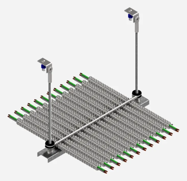
MC/AC cable on the HD trapeze.
Rated capacity

 ICC-ES Evaluated
PMG-1840
The rated load applies to the support assembly only; the attachment to structure is evaluated separately. Dry locations only, per the listing.
Custom order
Build a custom part number
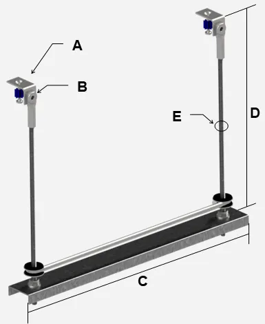
- A
- Fastener
- A18 · EC25-ACP32
- 1/4"-20 Post Nut with 1-1/4" x 0.145" Pin, 1" Embed.
- B
- Footprint on the rod
- B03
- Threaded: the all-thread rod threads directly into the post nut; no footprint.
- C
- Width
- C24 · 24 in.
- Width, 12 in. to 36 in.
- D
- Drop length
- D12 · 12 in.
- E
- Rod
- E01 · 1/4 in. all-thread rod
Built to order.
| Substrate | Fastener (tension) | Each rod | Assembly | Governed by |
|---|---|---|---|---|
| 2500psi NWC | 154 lbs | 154 lbs | 200 lbs | Support |
| 3000psi LWC with Metal Deck | 150 lbs | 150 lbs | 200 lbs | Support |
Seismic limit: per ASCE 7, power actuated fasteners are limited to 90 lbs of tension in Seismic Design Categories C (Ip = 1.5), D, E, and F.
Capacity by width
Published load by width
| Width | 12 in. | 18 in. | 24 in. | 30 in. | 36 in. |
|---|---|---|---|---|---|
| Uniform load | 200 lbs | 200 lbs | 200 lbs | 200 lbs | 200 lbs |
Uniform load over the 16g 1.5 in. cold rolled channel horizontal support. * = horizontal support bending governs (else the rated load). A single centered point load is limited to half the tabulated value; the configured assembly is further limited by the selected fastener per Section 01. Basis: reference document S.CRC (furnished upon request).
03 · Notes
From the Technical Data Sheet
- Enables airflow to eliminate bundling limitations. NEC 310.15(C)(1)(d).
- Rigid connection to structure eliminates the need to tie off to the ceiling grid below. NEC 300.11(A).
- Finish: zinc plated.
- Support spacing governed by the applicable local building code.
- Dry locations only, per the listing.
- Rated load carries a minimum 4:1 factor of safety on ultimate tested capacity per ICC-ES LC1041 and UL 2239.
- The rated load applies to the support assembly only; the attachment to structure is evaluated separately (Section 01).
- Drawings not to scale.
Downloads
Data sheet and ICC-ES report
Send the spec. We’ll build the support.
Size, drop, and service. We’ll spec the part number and quote the build.