
Snap with 1/4″ × 2″ wood hex lag
Straight into the framing.
A looped cable in a Snap, supplied with a 1/4″ × 2″ hex lag so it can be driven with a socket.
Assemblies ship individually wrapped and color coded by size, so a box of thirty does not arrive as a tangled mess. Sold 10/bag through 20′ and 5/bag at 35′.
Give us the size, drop and service and we’ll spec the part number and price the build.
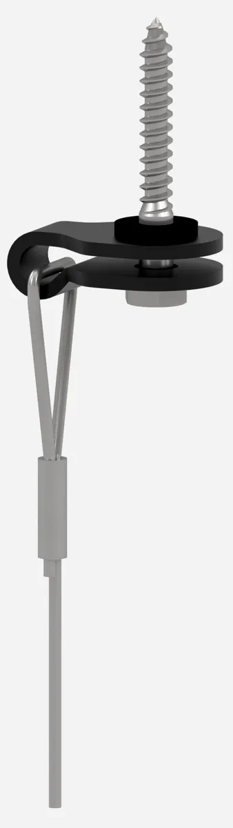
Snap and 1/4″ × 2″ wood hex lag.
Allowable tension load
Manufactured to ASTM A1023 and ASTM A931. This assembly is outside the scope of ICC-ES listing PMG-1840; refer to the Technical Data Sheet for capacities. Dry locations only, static overhead support only.
Allowable tension load
Capacities from the Technical Data Sheet
Allowable tension loads per Technical Data Sheet R0.2. This assembly is outside the scope of ICC-ES listing PMG-1840, so the sheet is the published source.
| Cable | Cable capacity | Solid sawn, glulam and CLT |
|---|---|---|
| #2, 3/32″ | 175 | 175 |
| #3, 1/8″ | 320 | 209 |
- Solid sawn, glulam and CLT: Panel face in CLT, spruce-pine-fir governs
Values are the allowable withdrawal of the hex lag at 1-11/32″ thread penetration, the maximum available on a 1/4″ × 2″ lag screw. Derived with the AWC Connection Calculator per the 2024 NDS, ASD, equation 12.2-1, CD = 0.90 for permanent load. Spruce-pine-fir governs among Douglas fir-larch, southern pine, hem-fir and spruce-pine-fir; glulam takes the specific gravity of its lamination species. The CLT value applies to the panel face. Not for installation in the narrow edge of cross-laminated timber, nor in end grain of any member. Where the hex lag withdrawal is lower than the ICC assembly rating, the hex lag governs the installed capacity. Connection to structure must be reviewed by the structural engineer of record.
Wood connections
Other fixings in this group
Part numbers
Read the callout
Assemblies are sold 10/bag through 20′ and 5/bag at 35′. Devices are ordered separately unless you ask for them packed with the assembly.
Add X2 or X3 at the end of the part number for double or triple tie cables. Many other options are available. Just let us know and we will get you specifically what works for your job!
| Part number | Description | Cable | Length | Pack |
|---|---|---|---|---|
| SC0206HL1 | 3/32″ Cable, 6′, Snap with 1/4″ × 2″ Wood Hex Lag | #2 | 6′ | 10/bag |
| SC0212HL1 | 3/32″ Cable, 12′, Snap with 1/4″ × 2″ Wood Hex Lag | #2 | 12′ | 10/bag |
| SC0220HL1 | 3/32″ Cable, 20′, Snap with 1/4″ × 2″ Wood Hex Lag | #2 | 20′ | 10/bag |
| SC0235HL1 | 3/32″ Cable, 35′, Snap with 1/4″ × 2″ Wood Hex Lag | #2 | 35′ | 5/bag |
| SC0306HL1 | 1/8″ Cable, 6′, Snap with 1/4″ × 2″ Wood Hex Lag | #3 | 6′ | 10/bag |
| SC0312HL1 | 1/8″ Cable, 12′, Snap with 1/4″ × 2″ Wood Hex Lag | #3 | 12′ | 10/bag |
| SC0320HL1 | 1/8″ Cable, 20′, Snap with 1/4″ × 2″ Wood Hex Lag | #3 | 20′ | 10/bag |
| SC0335HL1 | 1/8″ Cable, 35′, Snap with 1/4″ × 2″ Wood Hex Lag | #3 | 35′ | 5/bag |
Before you install
Limits that apply on every job
Follow capacity limits
Never overload SSF Cable Assemblies. Refer to the Technical Data Sheets for complete assembly capacities.
Take angle reductions
Assemblies not installed vertically take the published angle reduction, applied to the assembly rating. When cable is looped around round duct, the resulting angle shall not exceed 60°. Y-Accessories and Y-Assemblies may not be installed at angles greater than 60°.
Never join two cables
Never join 2 cables into a single device. Voids engineering and warranty.
Do not use for lifting
Static overhead support only. Not for lifting, rigging, or fall protection.
Dry indoor use only
Not for wet, chlorinated, or otherwise corrosive environments. Use SSF cable only; plastic-coated and third-party cables are not permitted with SSF devices.
Do not paint cables. Keep cables clean.
Install in final position before painting. Devices cannot be adjusted after paint contacts the cable. Cables must be free of oil and fireproofing prior to device installation.
Send the spec. We’ll build the support.
Size, drop, and service. We’ll spec the part number and price the build.